← blog · November 6, 2026 · 20 min read · part of torno →
vibeCAD: car parts from a chat window
How an experiment with Claude Code and build123d turned into an airbox fitted to a phone scan of the Micra's engine bay, why reviewing it on my phone was the worst part, and how that became torno, the workbench I now start every new part in.
Back in 2023 I wanted to print an adapter for the 200SX’s door speakers. The one off Thingiverse hit the door card, so I asked my cousin, who actually has a mechanical background, to help me design one from scratch. We measured everything, split it in three to fit the Ender’s bed, printed it, and still couldn’t turn our measurements into dimensions that fit. I ended up cutting MDF. That post is still up. The printer was never the problem. The CAD was.
This October I tried something different. I didn’t open a CAD program at all. I opened Claude Code in an empty folder and asked it to write the part in Python. A month later there is an airbox fitted to a 3D scan of the Micra’s engine bay, guitar and speaker stands, five roof spoilers to choose from, a keychain, and a desktop app built around the whole idea. I’ve been calling it vibeCAD.
What vibeCAD means here
The models are build123d, a Python CAD library on top of OpenCascade, the same geometry kernel FreeCAD uses. A part is a Python file. Run it and you get a real solid: STEP for CAD, STL for the slicer. There is no sketcher and no feature tree, just code, so Claude Code can write it, change it and test it like any other program.
My side of it: say what the part is for, give it real measurements, look at what comes out and say what’s wrong. Everything prints on a Bambu Lab P1S, so every model knows the bed is 256 mm and that 3 mm of that on each side is off limits.
The first test: a speaker stand
The first thing I asked for was boring on purpose: tilted desk stands for my KEF CODA 7s, which lie on their side on my office desk. Each speaker is 300 × 180 × 218 mm, so the stand is a frame that holds it, tips it up towards my ears and sits on foam so the desk doesn’t hum.
My prompts were things like “too much tilt, lower the tilt a bit to something close to 12 degrees”, “can you round the corners a bit” and “can we add a ‘luisgonc.’ like author signature at the front on a small corner?”. The model ended up with a Params block at the top, every size in one place, and 30 tests checking the dimensions.
Then I looked at it and asked: “It’s a bit weird how the speaker stoppers at the bottom are ‘floating’”
They were. Thirty passing tests, and none of them could tell that a block of plastic hung in mid air with nothing under it. Tests of dimensions don’t see printability. That turned into the first shared helper, a check that measures the overhang of every part in the pose it prints in, and a rule that has stuck ever since: after every build, look at the picture.
- The brief A 300 × 180 × 218 mm speaker on its side, at the far corner of a 1600 mm desk, aimed at me.
- Tilted 12° The stand tips the cabinet up. Rear tabs catch it; it rests on foam pucks in the top pockets, with more under the base.
- The front A wave of slots along the walls, the corners rounded, and the signature low on the front corner.
- Printed Two of them, flat on the base, no supports. They have held up fine.
I didn’t look at any of that in a CAD program. I already had nerv, a console I built to keep my Claude Code sessions in one window, and I gave it a panel that showed the STLs of whatever object a session was working on and rebuilt them on every save. That meant I could see the part and Claude couldn’t, which didn’t matter much for a stand and mattered a lot for what came next.
The real one: an airbox for the Micra
The Micra K11 is the Sucatisse track car. The battery tray is empty, and there is a K&N cone filter on a 70 mm pipe sitting more or less where the battery used to be, breathing hot engine air. The idea: a printed box around the filter that keeps the heat off and feeds it cold air from the opening behind the battery tray.
The opening prompt was a /goal with a Polycam scan of the engine bay (a .glb straight from my phone), two photos of the current intake, and two photos of the empty tray with the box’s outline and the air opening marked in red. Plus one line: “As we are doing with the rest of the object we must use python.”
Fitting a filter that isn’t in the scan
Claude converted the scan, rendered it from a few sides to look at it, and set up a frame on the tray plate. The scan had it 5° nose up, so every height in the design is measured square to the plate, not to the ground.
The intake isn’t in the scan, so where does the filter go? What is in the scan is the throttle body, and the pipe is a known shape: two 250 mm legs with a 45° bend. So Claude searched. It tried every filter position over the tray and kept only the ones whose pipe ends one silicone elbow away from the throttle body without passing through anything scanned.
The first version had skipped that search. It guessed the filter angle from the photos, 15° towards the wing, and that pipe ran straight into the brake fluid reservoir. The searched answer is 39° towards the wing and 20° down, with the base of the filter 150 mm above the tray.
Reviewing it on my phone
About an hour and a quarter in I was away from the desk and typed: “Can you share it in a way I can remotely on my phone see it?”
Claude wrote a page with three.js, the scan and the box inside it, and published it as a Claude Artifact, a private link I could open on my phone. That page became the design review for the rest of the session, which ran until the next afternoon. I’d orbit around the box on the phone, take a screenshot, draw on it with red, and send it back with a line of text:
- “There is a grid where there shouldn’t be any”
- “the grid structure doesn’t follow the lid surface on the corners, also avoid 90 degree corners”
- “from what I am seeing the filter is not pointing correctly”
- “The lid top panel could follow the countor of the filter and making the whole to be much lower and only high at the filter/tube locations”
And it worked, mostly. In that one session the box got a rib grid inside, swing latches that snap onto a bar and stay on as a hinge, a lid that’s a low deck with a pod shaped round the filter, the Sucatisse wordmark engraved into the deck, spacers that take the clamp load of the tray’s own bolts, and a snorkel that follows a few basic rules for an intake: a rolled lip at the mouth, no steps in the bore, and a taper of 7.6°, just under the 8° where the flow starts to come off the wall. Then a second, alternative snorkel that turns 90° to face the front of the car, for the same spout.
- The scan The engine bay from a phone, intake removed. 530k vertices in the original; this is 150k of them.
- Where the filter goes Found by search: the one pose whose pipe reaches the throttle body, misses everything and gives the lowest lid.
- The tub Flat floor, then 45° over the tray's lip and back down, so it prints without supports. Spacers under the two bolts.
- The lid A deck 36 mm above the seam with a pod round the filter. 242 × 247 mm, on a bed that allows 250.
- Latches and snorkel Three swing latches. The sleeve draws air from below the tray through a rolled lip.
- The other snorkel Same spout, but it turns through a quarter ellipse and faces the front of the car.
Where it hurt
The phone loop was also where it hurt, mostly in three places.
The open mesh. nerv’s panel kept saying the lid’s mesh was open. Claude kept saying it had fixed it. I kept sending screenshots: “Why do i still see the airbox-lid with open mesh?” It took me a while to realise Claude didn’t know which viewer I meant, and I had to say “its a nervs preview”. The hunt took a hundred minutes. There were two causes. The wordmark, traced from an SVG, had outline segments microns long that turned into sliver triangles when the mesh was welded. And there was a real 40 mm slit, where the edge of the pod ran inside the rounding of the deck. The solid was valid the whole time. A valid solid proves nothing about the exported file.
The lid that was 1.2 mm too big. “isn’t the lid bigger than a p1s can print?” It was 251.2 mm. The workspace check allowed 253, but nerv took 3 mm off every side of the bed, so the real limit was 250. Now there is one limit, and it comes from one place.
The fillets. Rounding an edge in OpenCascade failed three times on this part: a ValueError, then a segfault with exit code 139 and no traceback, then one more. Each time the fix was to stop asking the kernel to round a complex edge and draw the round into the shape instead. The pod is built from cross sections that already have their hollow curves in them.
The day after, I counted what that session had cost. These numbers are from the spec I wrote next:
| The intake session | |
|---|---|
| Length | 19 h |
| My messages | about 28 |
| Images I attached | 22 |
| of them, screenshots of a viewer | 13 |
| of them, with red ink drawn on | 9 |
| Turns correcting something Claude had called good | about 9 of 20 |
| Times the scan viewer was republished by hand | 16 |
| Throwaway scripts to load, slice and check the scan | 17 |
Claude got pixels, never places. A red circle on a phone screenshot says somewhere around here, and then the conversation is about where here is.
So far only the tub has been printed, in black ABS, to check it fits the tray. The forward snorkel won’t be printed until someone has looked under the car at what the scan shows in its way.
torno: what the intake was missing
Everything that cost time in that session fits into two problems. Claude can’t see what it made. And I can’t tell it exactly which face is wrong, or by how much.
So on October 8 I started torno, which is Portuguese for lathe. It’s a desktop app with a live 3D view of the model, Claude Code running in a pane next to it, and a set of tools for both of us:
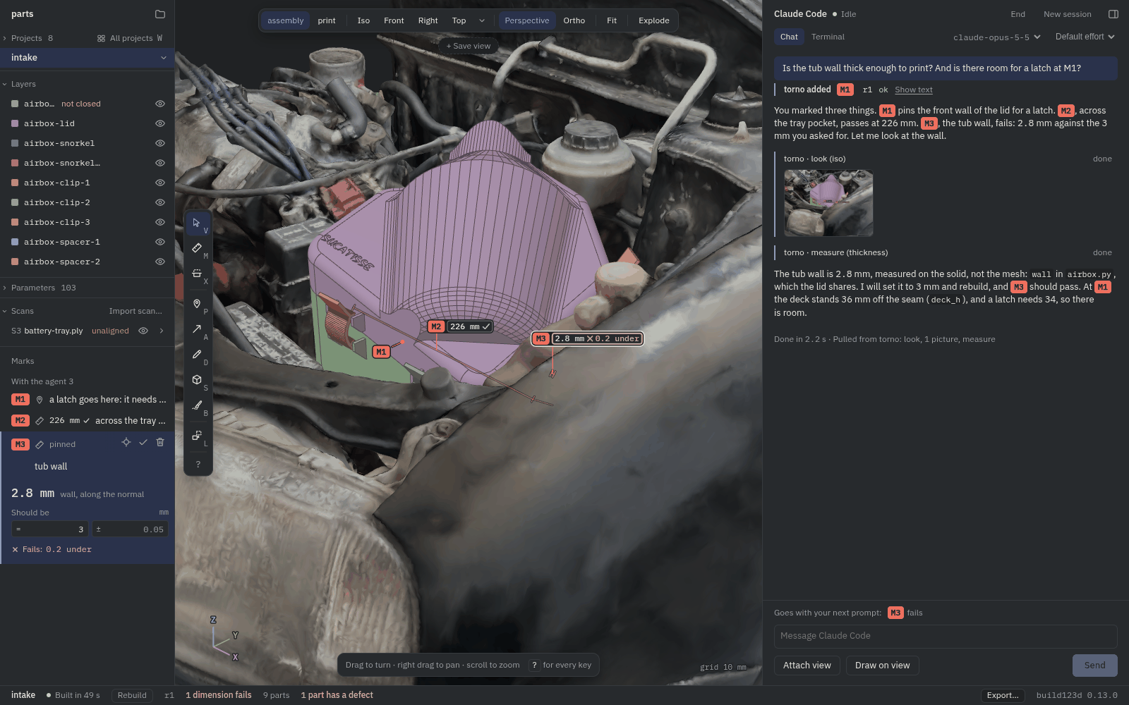
- Point, don’t describe. I pin a note on a face, draw an arrow or a stroke on the part, or measure a wall. Claude gets it with my next prompt as a reference like
lid/F12plus the exact numbers, not “the left side near the top”. - Claude can look. It has its own MCP tools:
look(a picture of exactly my view, marks included),measure(distances, angles and wall thickness on the real solid, not the mesh),section,checkfor printability and overlaps,diffbetween builds, andtry_fillet, which says which radius would work before a build dies on it. - Dimensions are tests. Give a measured wall the value it should have and it says passes or fails after every build, whoever changed the model.
- Scans are first class. Import the phone scan, align it, and check clearance against it without a single throwaway script.
- Every save rebuilds. When a build fails, the last good parts stay on screen and the traceback is one click away.
The model is still just the Python file. torno has no sketcher and no way to edit a solid by hand. It shows the part and carries what we point at.
Here is that loop in twenty seconds, on the airbox, inside the scan it was fitted to: a pin on the tub wall, a prompt asking for 3 mm, Claude looking and measuring, its edit, the rebuild, and the dimension turning to passes.
torno itself was built the same way, with Claude Code: a spec on day one, written from those intake numbers, then a plan per milestone and the work done by sub-agents. It’s an Electron and three.js window, a Python kernel that loads and tessellates the model in forked workers, and the real claude CLI in a terminal pane talking to torno’s MCP server on localhost. It runs your own Claude Code under your own login, and torno itself uploads nothing. It went public on November 4 after 633 commits.
Starting a part now
The difference shows most on a new part. In my objects workspace, every part starts from a generator that writes a model which already builds, a fast test set, a README and a brief.md. The rules for the agent came straight out of the intake:
- Brief first. What it’s for, what it holds, and measured sizes of everything it touches, a caliper number or a photo with a ruler. Every guess gets a name in the model and is listed at the top of every report until I confirm it. On the intake the real pipe and filter sizes arrived hours in and forced rework.
- Load direction before shape. Which way the force goes decides which way the layers run, and so which face goes on the bed. On the classical guitar stand I raised that seven hours in.
- Blockouts before details. Two or three rough shapes to pick from, no tests yet. The guitar stand went through six fully specced designs, most of them thrown away.
- Look before you talk. After every build Claude reads the report and looks at the pictures before saying anything about the shape.
- Write the lesson down. Anything that took more than a few minutes goes in
LESSONS.md, which every session reads first. It now holds things like why a smooth loft can swing hundreds of millimetres outside its own sections and still pass as valid, and how to write a 3MF that Bambu Studio will accept.
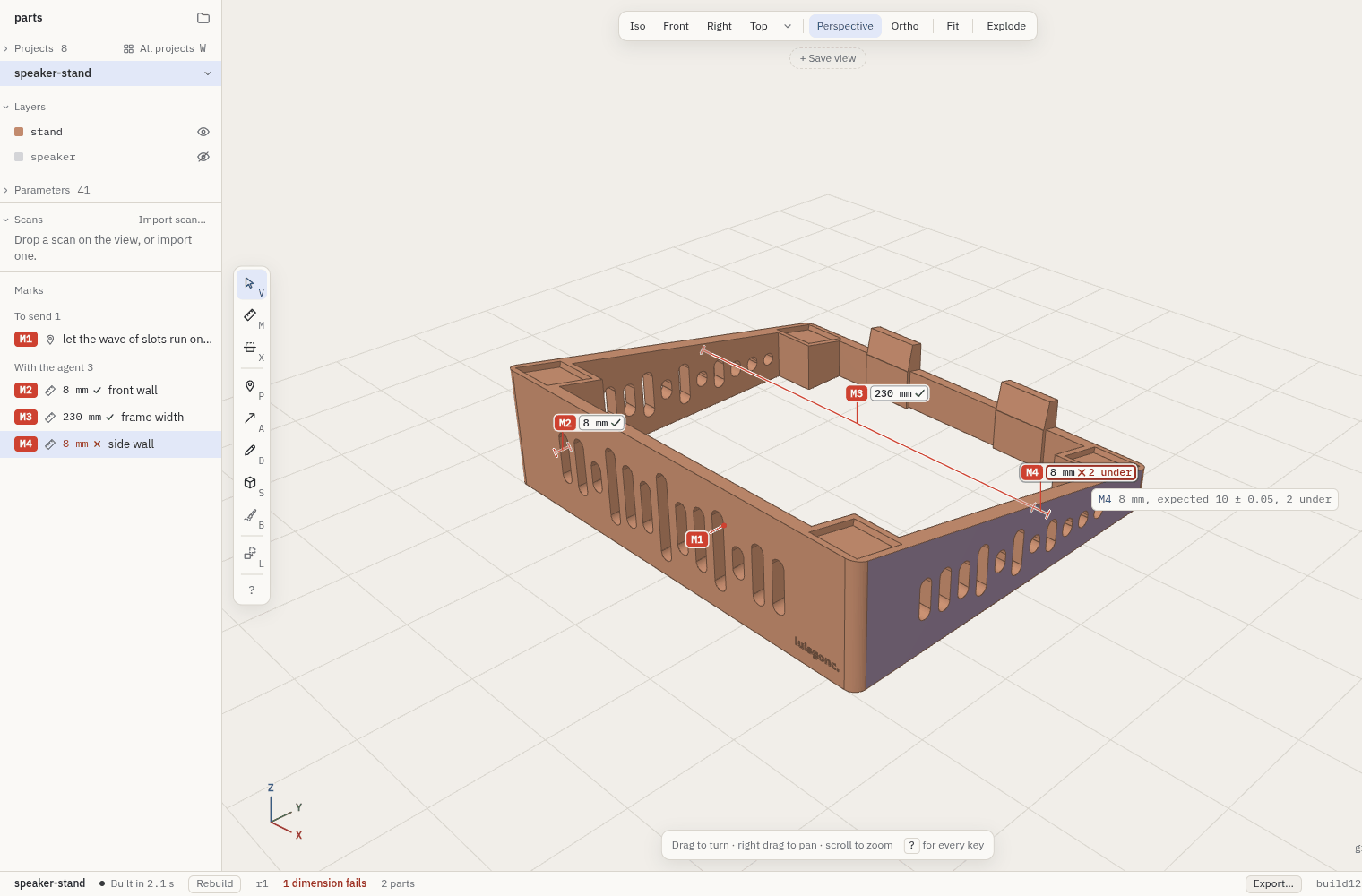
The speaker stand came back too, as the example in torno’s README. Those are dimension marks: the front wall and the frame width pass, and the side wall fails 2 mm under until the next build fixes it.
And a few of the parts that came after, each started from a description, photos or a scan:
- Keychain The Sucatisse wordmark traced from a photo, cream letters 1 mm proud of a dark backer. Claude wrote the 3MF so Bambu Studio gets a filament per part.
- Electric guitar stand A wishbone hanger for a Strat-style neck, printed as two mirrored halves so the layers run along the arms.
- Spoiler: ducktail One of five roof spoiler concepts drawn over a scan of the Micra's hatch and cut to it, so what touches the car is the scanned surface.
- Spoiler: biplane A lip on the hatch with a wing above it and a slot between, in the style of early 2000s rally cars.
- Spoiler: swan neck A wing hung from its top by two pylons, with a small gurney flap. None of the five is on the car yet.
Try it
torno is open source under Apache-2.0, at github.com/luisg0nc/torno, with a landing page and the manual at torno.luisg.me. It runs on Linux and macOS, needs Node 22, uv and a logged in Claude Code, and checks all of that on its first screen. Open the example gives you an enclosure with a rattling lid and a few marks to try everything on, in a temporary copy.
What I’d tell anyone starting:
- It’s great at prismatic parts with sizes you measured. Brackets, enclosures, holders, a lid and a box, hole patterns.
- It needs more from you for a part that has to fit a place you can only scan, and for an assembly of more than three or four parts that touch.
- It’s bad at organic shapes described only in words, gears and threads written by hand, and sizes read off a photo.
- Give it numbers. A caliper reading, a scan or a dimension mark beats any description. Almost every part that didn’t fit had a guessed size somewhere.
Three years ago I gave up on a speaker adapter and cut MDF. This month an airbox went from a phone scan to the printer, the tub of it at least, and I never opened a CAD program.